The new Microlink themocouple data logger not only logs temperature but can also measure voltage, flow, level etc. Additionally, it provides digital I/O and event and frequency counting.
Price: 830 GB pounds.
Features
- Monitor 16 thermocouples or voltage signals
- Built-in linearisation for B-, E-, J-, K-, N-, R-, S- and T-type thermocouples
- Automatically detect broken thermocouple leads
- With extra hardware also measure strain, current and pH
- Read data over an Ethernet network or over the Internet
- Includes the powerful yet easy-to-use Windmill Software for Windows: no programming required
- Automatic ranging lets the software match the signals as closely as possible
- Integrating analogue-to-digital converter reduces electrical noise
- Use Windmill to select the resolution of the A-D converter from 12- to 18-bits: choose high resolution or high speed
- Automatic recalibration
- Set two alarms on each input
- Use the 851-TC for real-time data acquisition on your PC or for stand-alone data logging
- Free technical support for life and money-back guarantee
Themocouple Measurement
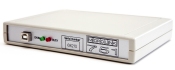
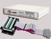
The system comprises a Microlink 851 measurement unit, an isothermal box, Windmill data acquisition and control software and technical support for life.
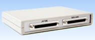
Connect the thermocouple wires to screw terminals in the Microlink isothermal box. This keeps the temperature of the thermocouple junctions constant, measured by a cold junction sensor in the box. Plug the isothermal box into the Microlink 851 using its ribbon cable. The isothermal box will also detect broken thermocouple leads for you. If you need more information on monitoring thermocouples, we have a tutorial on computerised themocouple measurement on our Data Acquisition Intelligence site, or contact our Technical Support Team.
The 851 provides 32 digital I/O lines, arranged in four groups of 8. Use Windmill software to choose whether each group is an input or an output. You can read or set the state of each line individually, or switch several lines at the same time.
The 851 has eight counters which you can use for counting events or measuring frequency.
When counting events, you can use the counters in two modes: accumulating count and resetting count. In accumulating count the counter keeps going until you reset it from software. In resetting count the counter shows the number of pulses since the last reading.
When measuring frequency you can count over 1 or 10 second intervals.
You can scale counts using Windmill software. For example if the pulses came from a flow meter which produced one pulse for every 50 millilitres, a scale factor of 0.05 would give a reading in litres.
The counters are found on 8 of the digital input and output lines. You can use any of these you don't need for counting as normal digital inputs: the counts are always maintained even if you don't plan to use them.

Set Alarms on Each Input
You can set two alarm levels on each input, and specify what happens when an alarm threshold is crossed. For example, an alarm could be sounded or other equipment switched on.
Software
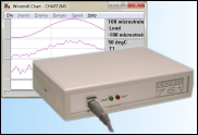
Windmill Software is included in the 851-TC package. This modular suite offers data logging, charting, alarm indication, output control and real-time links to other applications like Excel. You can also add process mimic generators, sequence control and many other modules. Should you wish to program the hardware yourself, you can use the IML Tools to do so.
Free Technical Support and Money-Back Guarantee
All our systems come with free technical support for life and a guarantee that if you aren't satisfied we'll give you your money back.
 Dimensions (mm)           180 x 120 x 40
 Maximum logging speed     10 scans a second
 Memory                    65000 scans
SOFTWARE
 Operating system          Windows 10, 8, 7 64-bit, 7 32-bit
 Vista, XP, 2000 or 98
ANALOGUE INPUTS
 Maximum # inputs          16 differential
 Built-in linearisation for B-, E-, J-, K-, N-, R-, S- and T-type thermocouples
Maximum safe input voltage:
 Power supply on           ±48 V
 Power supply off          ±33 V
 Transient                 ±300 V
Amplifier:
 Ranges (V)                ±0.01, ±0.1, ±1, ±10
 Common mode range         ±13 V
 Relative accuracy of ranges:
 gain = 1000               ±0.1%
 gain = 1, 10, 100         ±0.05%
Analogue to Digital Converter:
 Maximum linearity error   ±0.02%
 Resolution    Integration Time    Samples/Second
 12 bits         2.5 msec          80
 13 bits         5 msec            64
 14 bits        10 msec            48
 15 bits        20 msec            32
 16 bits        40 msec            16
 18 bits       160 msec             6
DIGITAL INPUTS/OUTPUTS
 Maximum # inputs          32
 Maximum # outputs         32
 (selected through Windmill in ports of 8 lines)
 Power-up state            all inputs
 Compatibility             TTL and 5 V CMOS, can be made
 contact closure compatible
 Range                     0 to 5 V
 Output capability         15 LSTLL loads
 Maximum I/O speed         160 channels per second
COUNTERS
 Maximum # counters        8
 Resolution                23 bits
 Maximum count (events)    1000000
 Maximum frequency         5 kHz
 Minimum pulse width        500 µseconds
 Frequency gate times      1 or 10 seconds
 Compatibility             TTL, 5 V CMOS, can be made
 contact closure compatible
 Input voltage range       0 to 5 V